
EXFO / MAX-730D field guide
Read the whole link. Find the event that matters.
Prepare the MAX-730D, define the tested span and turn an OTDR trace into a reviewable fiber record.
01 / Understand the task
Start with the link, not the pulse width.
Document the endpoints, fiber type, expected length, splitter topology and required acceptance tests. Then configure the installed MAX-730D optical and software options for that job. This workflow uses the OTDR application; iOLM is a separate licensed workflow.

Protect the first connection
Inspect both mating end faces, clean when needed and inspect again. A dirty launch connection can consume dynamic range and obscure the events you are trying to diagnose.
Define the real span
Use launch and receive fibers when the test plan needs the first and last link connectors characterized. Set their boundaries so accessory fiber is not mistaken for the installed link.
Read trace and table together
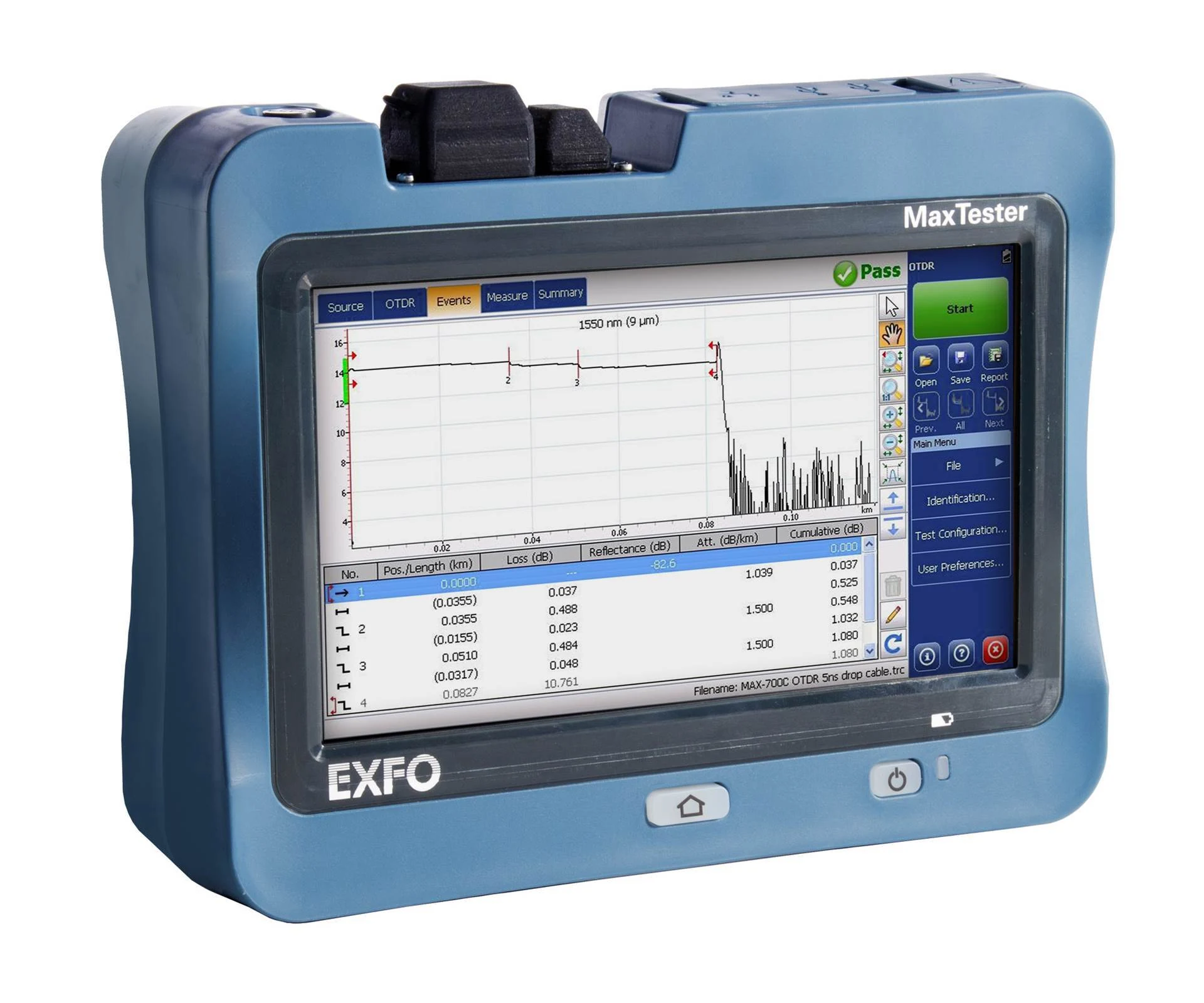
Locate each important event on the trace and compare its distance, loss and reflectance with the event table. Resolve questionable geometry or detection before reporting acceptance.
02 / Explore the system
Connect the test path to the trace
Select each stage to connect the setup, the observation and the record.
Identify the instrument configuration, connectors, fiber type and required wavelengths. Launch and receive fibers help expose the link-end connections to the OTDR.
03 / Put it to work
Know the controls. Follow the sequence.
Use the original manufacturer figures alongside the action each one supports.
Configure the fiber before the test
Link Definition brings fiber characteristics and detection settings together. Use the actual fiber data and project criteria; the numeric values are manufacturer examples.
EXFO OTDR User Guide v20.0.0.1, PDF p.48 / printed p.37.
Record the job
Create a consistent link ID with near end, far end and direction. Record the installed optical option and required wavelengths, then check storage and the destination for the original trace files.
Inspect, clean, inspect
With the link confirmed dark and test sources off, inspect the test port, launch/receive ends and link ends using a suitable video inspection probe. Clean contamination with the appropriate fiber tool and reinspect before mating.
Connect the span
Connect the matched launch fiber between the OTDR and the near end, and the receive fiber at the far end when required. Avoid tight bends in the test leads. Confirm the actual connection type and selected OTDR port.
Set fiber and analysis information
In Test Configuration, review Link Definition and the fiber characteristics for each wavelength. Use the cable manufacturer’s IOR/group index and appropriate backscatter information. Set distance units and agreed pass/fail criteria; do not copy values from a manual screenshot.
Set launch and receive boundaries
In the OTDR acquisition settings, use Launch and Receive Fiber and select the length-based or event-based method. Enter the actual accessory information and confirm the boundaries on the resulting trace.
Acquire a useful trace
Select the required wavelengths and a range covering the full setup. Start with the appropriate automatic settings or the approved job configuration. Adjust pulse width and acquisition duration only to resolve a specific issue: reach, noise or closely spaced events.
Review and repeat where needed
Inspect the first connector, far end and every unexpected event. Compare wavelengths and perform the required reverse-direction test. A splitter or noisy tail must not be mistaken for the end of the intended span.
Save, export and verify
Save the native traces with the link ID and acquisition information. Generate the requested report, copy the complete results to the project destination and reopen a sample. Preserve original files and record any retest or analysis change.
04 / Inspect the result
Recognize what needs a closer look.
Use the record and the setup together when deciding what to investigate.
Resolve close events deliberately
A large reflection can conceal nearby detail while the receiver recovers. A shorter pulse may separate close events but reduce reach; longer averaging reduces noise rather than eliminating a dead zone. Compare acquisitions when the first trace cannot answer the question.
Use both directions when the plan requires them
Backscatter differences can make a splice look better from one direction than the other. Preserve correctly paired directional traces and use the approved bidirectional analysis workflow; do not average unrelated fibers or wavelengths.
Keep acceptance tied to the contract
The OTDR locates and characterizes events. Complete the separately specified OLTS insertion-loss test as well; a green OTDR result alone does not replace the required loss-test evidence.
Save evidence before changing analysis
Keep the original acquisition. Record subsequent threshold or event changes so a reviewer can distinguish measured data from revised interpretation.
The first connection dominates the trace
Stop testing, turn off the source and revisit inspection of both mating faces and the adapter. Check the launch fiber for damage or bending before increasing the pulse width.
The far end disappears into noise
Confirm the intended span and range. Review the loss and splitter topology, then compare a longer acquisition or suitable pulse setting. Do not declare missing downstream events acceptable because they were not detected.
The distance disagrees with the cable route
Check units, IOR, launch offset and endpoint identity. Optical fiber length can differ from jacket or route length; do not change IOR simply to force agreement.
05 / Deliver with evidence
Finish with a record someone else can use.
Work through the checks before the job leaves your device.
Guide scope & manufacturer resources
Configuration and edition
MAX-730D within the MAX-700D family; OTDR application. Wavelengths, live-fiber capability, connectors and software depend on the ordered configuration.
Manufacturer screenshots contain illustrative settings and sample results; captions identify these explicitly. Editorial workflow guidance supplements the cited operating manuals; apply the installed instrument configuration and the project acceptance specification.
Manufacturer figures retain their published example values and status messages. Use the settings and complete operating instructions for the installed configuration. Independent record and handoff checks are Fiber Equipment Supply recommendations.
The contextual landscape is an AI-created illustration; workflow graphics are authored teaching diagrams. These visuals are not recorded inspections or measurement results.
Manufacturer references
- MAX-730D product and available configurations
Official product page, accessed September 15, 2026. - EXFO OTDR User Guide, v20.0.0.1
Manufacturer-authored manual, retrieved from an indexed document mirror after EXFO’s download server failed. MAX-700D explicitly covered. Printed pp.16–25 safety, 27 connections, 35–39 fiber data, 82–96 acquisition and span definition, 103 units; later trace analysis and reporting chapters. Release date not stated in the retrieved front matter. - OLTS & OTDR: A Complete Testing Strategy
Fluke Networks; accessed September 15, 2026. Distinguishes insertion-loss acceptance from OTDR characterization.