
Fluke Networks / OptiFiber Pro HDR · OFP2-200-S field guide
See the event. Explain the result.
Use the HDR singlemode OTDR workflow to inspect the link, review EventMap and deliver evidence that survives a second look.
01 / Understand the task
A specific kit, with specific capabilities.
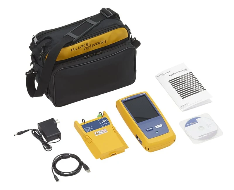
OFP2-200-S combines a Versiv 2 mainframe with the HDR singlemode OTDR module for 1310/1550 nm. The manufacturer lists inspection and launch accessories in separate Si kits. Assemble the accessories your job requires before arriving at the fiber.

Match the HDR connector
The HDR port uses an APC end face. Use a compatible APC connection at the instrument; mating a PC/UPC plug can damage the port and compromise the trace.
Set the job before TEST
Review the project, ID, fiber type, test type, wavelengths and limit. Use launch compensation where required by the measurement plan.
Read all three result views
EventMap provides context; TABLE lists measurements; TRACE reveals the signal behind the interpretation. Investigate the same event across these views before accepting the result.
02 / Explore the system
Connect the test path to the trace
Select each stage to connect the setup, the observation and the record.
Confirm the HDR singlemode module, the APC test-port interface and compatible launch/receive fibers. Complete the matched launch-compensation workflow when required by the selected test and acceptance plan.
03 / Put it to work
Know the controls. Follow the sequence.
Use the original manufacturer figures alongside the action each one supports.
Connect the HDR with launch and tail cords
The original illustration shows an out-of-service PON test with the OLT disconnected. Its APC instrument connection and separated test boundaries are the details to carry into the job.
Fluke Versiv Technical Reference Handbook Rev.14, February 2025, PDF p.469 / printed p.447, Fig.177; original vector figure rendered from the PDF.
Prepare the project and test kit
Identify the actual HDR module, software version and cable endpoints. Add the required video inspection probe, cleaning tools and compatible singlemode launch/tail cords; do not assume these are included with the base 200-S kit.
Inspect and connect correctly
Confirm the fiber is dark. Inspect, clean when needed and reinspect the relevant port and lead/link end faces. Use APC at the HDR instrument port and compatible connections at the other ends.
Review the test setup
On the home screen, confirm the correct project and cable ID. In TEST SETUP choose the fiber type, required 1310/1550 wavelengths and applicable limit. Select Auto OTDR for a point-to-point link or the appropriate PON mode for passive splitters.
Set launch compensation when required
Use launch/tail cords to characterize end connections where the plan requires it. Tap SET COMP, select the method and follow the displayed connection sequence. Confirm the actual boundaries; a sample cord length is not a universal setting.
Run and watch connection quality
Tap TEST or use the test key. Review the port-connection quality gauge. If it is poor, stop and investigate the connection instead of accepting a noisy trace or simply widening the pulse.
Read EventMap, TABLE and TRACE
Select the important event in EventMap, review its measurements and inspect the corresponding trace region. Check the far-end identity, splitter interpretation and any unexpected loss. A PASS label is meaningful only against the correct setup and limit.
Resolve ambiguity with a controlled retest
Use Manual OTDR only to answer a specific unresolved question about range, close events or noise. Change one relevant setting at a time and retain the earlier result. Complete correctly paired bidirectional tests when required.
Save and check the handoff
Confirm that the result has been saved under the intended ID. Transfer the complete project using the supported LinkWare/USB workflow for the installed version, create the report and reopen sample results. Include the separately required OLTS evidence.
04 / Inspect the result
Recognize what needs a closer look.
Use the record and the setup together when deciding what to investigate.
Resolve close events deliberately
A large reflection can conceal nearby detail while the receiver recovers. A shorter pulse may separate close events but reduce reach; longer averaging reduces noise rather than eliminating a dead zone. Compare acquisitions when the first trace cannot answer the question.
Use both directions when the plan requires them
Backscatter differences can make a splice look better from one direction than the other. Preserve correctly paired directional traces and use the approved bidirectional analysis workflow; do not average unrelated fibers or wavelengths.
Keep acceptance tied to the contract
The OTDR locates and characterizes events. Complete the separately specified OLTS insertion-loss test as well; a green OTDR result alone does not replace the required loss-test evidence.
Save evidence before changing analysis
Keep the original acquisition. Record subsequent threshold or event changes so a reviewer can distinguish measured data from revised interpretation.
Do not confuse an OSP shortcut with an acceptance rule
The HDR handbook discusses long outside-plant tests that do not need launch/tail cords. Use the customer’s specified method and include them when end connectors must be characterized; DataCenter OTDR requires launch compensation.
Port quality is outside the good range
Turn off test light and inspect both end faces, the adapter and the test lead. A poor connection expands the dead zone and reduces usable signal; a longer test does not repair it.
A passive splitter appears as a large loss
Check the selected test type and actual topology. Ordinary Auto OTDR does not identify splitters the way a PON test does. Reconfigure deliberately rather than relabeling an unexplained event.
Length or acceptance changes unexpectedly
Verify fiber type/IOR, units, compensation boundaries and the selected limit. Some limits use measured length and connection counts; changing these can alter acceptance without changing the fiber.
05 / Deliver with evidence
Finish with a record someone else can use.
Work through the checks before the job leaves your device.
Guide scope & manufacturer resources
Configuration and edition
OFP2-200-S: HDR singlemode 1310/1550 nm kit. This dark-fiber guide does not apply 1490/1625 options or multimode capability to this model.
Manufacturer screenshots contain illustrative settings and sample results; captions identify these explicitly. Editorial workflow guidance supplements the cited operating manuals; apply the installed instrument configuration and the project acceptance specification.
Manufacturer figures retain their published example values and status messages. Use the settings and complete operating instructions for the installed configuration. Independent record and handoff checks are Fiber Equipment Supply recommendations.
The contextual landscape is an AI-created illustration; workflow graphics are authored teaching diagrams. These visuals are not recorded inspections or measurement results.
Manufacturer references
- OptiFiber Pro OTDR family: OFP2-200-S kit
Official models table confirms HDR, Versiv 2 and 1310/1550 nm; separate Si kit lists inspection/launch accessories. Accessed September 15, 2026. - Versiv Technical Reference Handbook, Rev.14
February 2025. Chapter 12, printed pp.419–450: HDR module, setup, cord compensation, connection quality and test procedure; later result analysis and project-management chapters. Manufacturer download listing title differs from the PDF; this guide identifies the actual PDF revision. - OLTS & OTDR: A Complete Testing Strategy
Fluke Networks; accessed September 15, 2026. Distinguishes insertion-loss acceptance from OTDR characterization.