
VIAVI Solutions / T-BERD / MTS-2000 field guide
One platform. A traceable test workflow.
Configure the installed OTDR module, control the test boundaries and keep every result tied to the right fiber.
01 / Understand the task
The module defines the measurement.
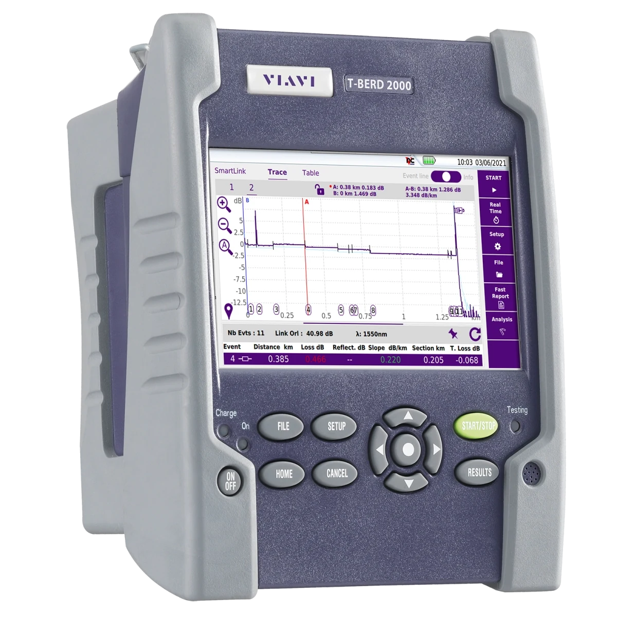
T-BERD/MTS-2000 identifies the platform, not a complete set of optical capabilities. Record the installed 4100-series module and application version before selecting a configuration. Wavelengths and acquisition choices vary with that module.

Load a deliberate setup
Use a verified configuration for the cable and job. Check it against the installed module rather than assuming a saved setup is universal.
Keep both ends visible
Launch and receive fibers move the link connectors away from the instrument reflection and unconnected far end. Define the boundaries and decide whether the end connections belong in overall loss.
Treat alarms as a review queue
Open the flagged event, inspect the corresponding trace and investigate the physical connection. A result color follows configured thresholds; it is not a substitute for checking the test setup.
02 / Explore the system
Connect the test path to the trace
Select each stage to connect the setup, the observation and the record.
The MTS-2000 platform hosts the measurement module. Confirm the installed OTDR module and application before selecting fiber, connector and acquisition settings.
03 / Put it to work
Know the controls. Follow the sequence.
Use the original manufacturer figures alongside the action each one supports.
Inspect before you connect
Follow the inspection decision loop at each mating pair. Reinspection confirms whether cleaning actually removed the contamination.
VIAVI OTDR 700MAN201 Rev.011, November 25, 2025, PDF p.19 / printed p.3, Fig.1.
Identify platform, module and fiber
Record the platform, module, software, cable ID, endpoints and direction. Confirm the module supports every required wavelength and the planned point-to-point or PON test.
Prepare clean connections
Inspect the test port and every lead/link end. Clean only as needed, reinspect and connect matching polish types. Keep clean dust caps available and protect disconnected ends.
Load or establish the setup
Open Expert OTDR setup and load the verified job configuration if one is supplied. Review the distance units, acquisition choices, link identification, alarm limits and file destination before testing.
Define launch and receive fibers
In General settings, enable the applicable launch/receive cable definitions by event or length. Review Include Link Connection so the overall-loss calculation includes or excludes the end connections exactly as the test plan requires.
Match acquisition to the question
In Acquisition, select the supported wavelengths and intended mode. SmartAcq+ combines multiple pulse acquisitions; the Rev.011 manual does not recommend it for bidirectional testing. Use the appropriate approved mode for that requirement.
Verify fiber parameters and run
Review IOR and relevant fiber parameters in the advanced setup; use the fiber specification, not a sample screenshot. Acquire the trace and check that it covers the intended far end and the required event detail.
Investigate the event list
Inspect unexpected losses, reflectance or missing events on the trace. Compare wavelengths, check the physical location and repeat the required direction after any repair. Do not relax alarms to create a passing report.
Save the complete evidence
Use the configured file path and naming rule, retaining native results as well as reports. Copy the results to the project record and verify that a representative file reopens with the correct ID, direction and settings.
04 / Inspect the result
Recognize what needs a closer look.
Use the record and the setup together when deciding what to investigate.
Resolve close events deliberately
A large reflection can conceal nearby detail while the receiver recovers. A shorter pulse may separate close events but reduce reach; longer averaging reduces noise rather than eliminating a dead zone. Compare acquisitions when the first trace cannot answer the question.
Use both directions when the plan requires them
Backscatter differences can make a splice look better from one direction than the other. Preserve correctly paired directional traces and use the approved bidirectional analysis workflow; do not average unrelated fibers or wavelengths.
Keep acceptance tied to the contract
The OTDR locates and characterizes events. Complete the separately specified OLTS insertion-loss test as well; a green OTDR result alone does not replace the required loss-test evidence.
Save evidence before changing analysis
Keep the original acquisition. Record subsequent threshold or event changes so a reviewer can distinguish measured data from revised interpretation.
Check the end-connection accounting
A correct launch length does not by itself answer whether an end connector is included in overall loss. Review Include Link Connection alongside the boundary definitions and the acceptance plan.
Reflectance alarm at the launch-cable end
Inspect and clean the mating faces; check seating, damage and connector-polish compatibility. The manufacturer’s example highlights these as possible causes, not a diagnosis of your fiber.
Expected wavelengths or modes are unavailable
Check the installed module and enabled application. The platform alone does not establish a wavelength set, PON capability or FiberComplete functionality.
Saved data cannot be matched to the fiber
Stop the sequence and reconcile cable IDs, endpoints, direction and naming fields. Reopen the last result before allowing the next automatic name to propagate an error.
05 / Deliver with evidence
Finish with a record someone else can use.
Work through the checks before the job leaves your device.
Guide scope & manufacturer resources
Configuration and edition
T-BERD/MTS-2000 with a compatible 4100-series OTDR module. Expert OTDR workflow based on 700MAN201 Rev.011; available functions depend on module and software.
Manufacturer screenshots contain illustrative settings and sample results; captions identify these explicitly. Editorial workflow guidance supplements the cited operating manuals; apply the installed instrument configuration and the project acceptance specification.
Manufacturer figures retain their published example values and status messages. Use the settings and complete operating instructions for the installed configuration. Independent record and handoff checks are Fiber Equipment Supply recommendations.
The contextual landscape is an AI-created illustration; workflow graphics are authored teaching diagrams. These visuals are not recorded inspections or measurement results.
Manufacturer references
- T-BERD/MTS-2000 platform
Official platform/module information, accessed September 15, 2026. - OTDR application User Manual, 700MAN201 Rev.011
November 25, 2025. Printed pp.2–6 connection preparation; pp.34–55 Expert OTDR configuration and file settings; pp.60–66 event review; chapter 4 file management. Exact screen layouts may differ with later software. - OLTS & OTDR: A Complete Testing Strategy
Fluke Networks; accessed September 15, 2026. Distinguishes insertion-loss acceptance from OTDR characterization.